The compression system is the basic of operation of the refrigeration units described in this chapter. One must understand the system to accurately diagnose (identify) mechanical difficultties. Many types of compression mechanisms are explained to hlp the service tecnician become familiar with their basic operation.
The arrangement of the units of study in this chapter will be in the same other as the arrangement of the part in a refrigeration system. Beginning with the evaporator (where the heat absorbed), the squence (order of study) is through the condenser, (liquid receiver, filter -drier, liquid line, refrigerant control and back into the evaporator.
Necessary details concerning the construction and operation of the parts - as well as of various types of these mechanisms- are explained fully. Included are necessary temperature and motor controls.
1. LAW OF REFRIGERATION
All refrigeration systems depend on five thermal laws:
a. fluida absorb heat while changing from liquid state to a vapor state and give up heat in changing from a
vapor to a liquid.
b. The temperature at which a change of state occurs is constant during the change provided the preassure
remain constant.
c. Heat flow only from a body which is at highertemperature to a body which is at a lower temperature (hot to
cool).
d. Metallic parts of the evaporating and condensing units use metals which have a hight heat conductivity
(copper, brass, aluminium).
e. Heat energy and other forms of energy are interchangeable. for example, electricity may be converted to heat: heat to electrical energy and heat to mechanical energy.
2. COMPRESSION CYCLE
The compression cycle is so named because it is the compressor which changes the refrigerant vapor from low pressure to hight pressure. This pumping causes the transfer of heat energy from the inside of the cabinet to the out side. Since the compression machine transfers heat from one place to another, it may also be called a head pump.
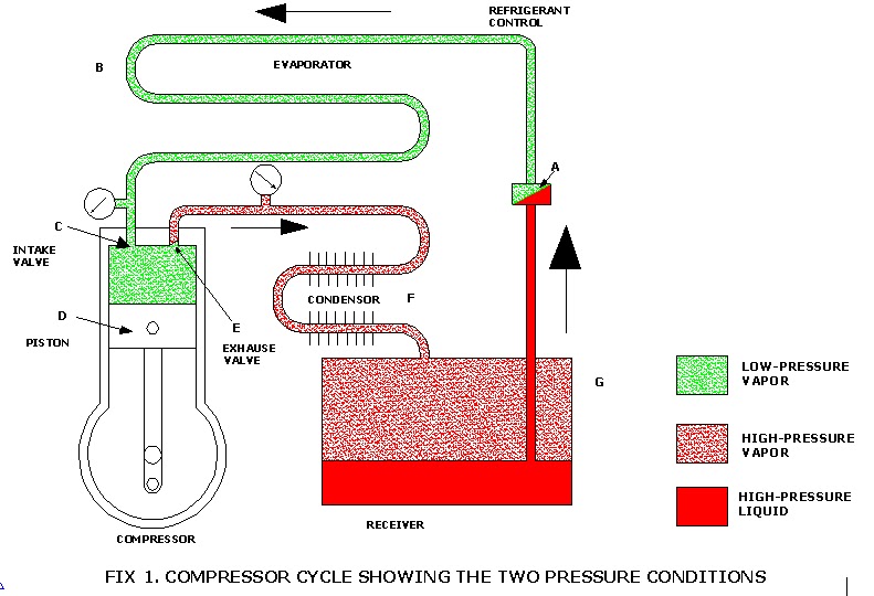
Fig. 1. Compression cycle showing the two pressure conditions. Low-pressure side extends from refrigerant control, A, through evaporator, B. to the compressor intake valve, C. high-pressure side begins in the cylinder above piston, D. on the compressor stroke. It extends from exhaust valve, E. through condenser, F. liquid receiver, G. and liquid line, to refrigerant control, A.
A refrigerating system consists principally of hight-pressure side and a low-pressure side. Fig 1.
A refrigeration cycle follows these steps : From the liquid receiver, G, liquid refrigerant, at a hight pressure flows throughthe refrigant control, A, (a pressurew reducer). It moves into the evaporator, B, The evaporator is under a low pressure. Here the liquid refrigerant vaporizes (boils) and absorbs heat.
The vapor then flows into the compressor through the intake valve, C, back into the compressorcylinder. The piston, D, on the compression stroke, squeezes the vapor into a small space with an increase in temperature.
In fig 1. the compressed high-temperature vapor is pushed through the exhaust valve, E. into the condenser, F, In the condenser, heat from the refrigerant is passed on to the surrounding air. In giving up this heat, it returns to a liquid and is stored in the receiver. From here cycle is repeated.
In operation, the apparatus transfers heat from one place to another place. That is, it takes heat from the inside of a refrigerator to the out side air or from the water of the water cooler to the outside air. This action may be compared to using a sponge to pick up water in one pace and releasing it in another by squeezing it.
To have a tranfer of heat, there must be a temperature difference. To get the temperatur difference, there must be a low-pressure side ( heat absorber ) and high pressure side ( heat dissipator ). Various compression cycles are ilusstrated in this chapter.
3. OPERATION OF COMPRESSION CYCLE
Fig. 2. illustrates a typical compression cycle as used in a domestic refrigerator. It has certain necessary parts which will be explained.
In any compression refrigeration system, there are two different pressure conditions. One is called the low side and the other the high side. The evaporator is in the low side. Heat is absorbed in the low side.
The accumulator, suction line and entrance to the compressor suction valve are also on the low side.
The condenser is in the high side, where the heat is released from the refrigerant. The compressor exhaust valve, liquid receiver ( if used , liquid line filter-drier, liquid line and the refrigerant control are also on the high side.
A thermostat maintains correct operating temperature by controlling the motor electrical circuit.
EXTERNAL DRIVE COMPRESSORS
An external drive (open) compressor is bolted together. Its crankshaft extends through the crankcase. The crankshaft is driven by a flywheel (pulley) and belt or it can be driven directly an electric motor.
HERMETIC COMPRESSORS
The motor in hermetic compressor is sealed inside a dome or housing with the compressor and directly connected to the compressor. A crankshaft seal is not needed.
TYPES OF COMPRESSORS
There are four basic types of compressors in use :
1. Reciprocating (piston-cylinder)
2. Rotary
3. Screw type
4. Centrifugal.
 Fig . 1.Reciprocating, (piston-cylinder). Bolted type hermetic motor compressor assembly.
Motor is at right and compressor at left. (bitzer co.)

Fig. 3. Screw type. hermetic motor compressor.
(bitzer co)
Source :
Modern refrigeration and air conditioning by Andrew D. Althouse, B. S.dan kawan-kawan
